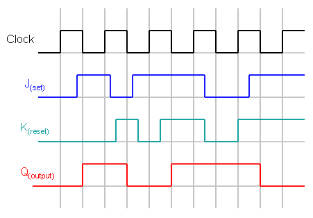
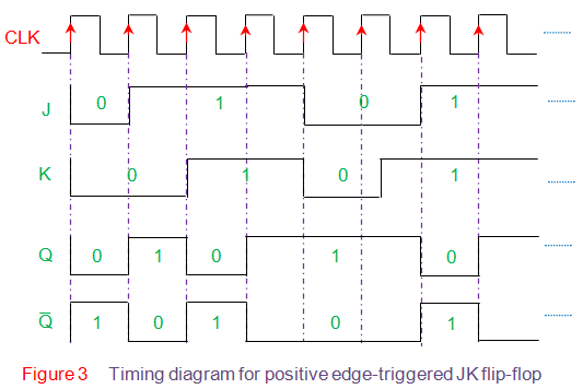
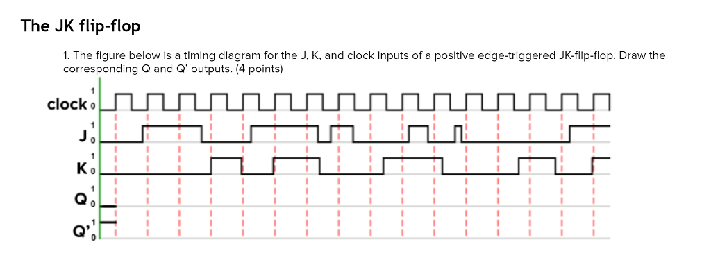
Solved the jk flip flop 1 the figure below is a timing
Table of Contents
Table of Contents
If you’re working with jk flip flops, you know that drawing a timing diagram can be difficult. However, with a little bit of know-how, you can master the process and create clean, accurate diagrams that will help you understand how your circuit is working.
When it comes to drawing timing diagrams for jk flip flops, there are a few issues that tend to plague beginners. For one thing, it’s easy to get confused between the jk flip flops themselves and the signals they’re generating. Additionally, there are a lot of different symbols and notations that can be challenging to keep track of.
The good news is that there’s a straightforward process you can follow to create a useful timing diagram. The first step is to familiarize yourself with the jk flip flop circuit itself. This will help you understand how to read the signals and ensure that you’re depicting them accurately.
Next, you’ll need to identify which signals you want to show on your diagram. Typically, this will include the j and k inputs, the clock signal, and the q and q-bar outputs. By selecting these signals and plotting them out over time, you’ll be able to create a visual representation of how the circuit is behaving.
How to Draw Timing Diagram for JK Flip Flop: A Personal Experience
When I was first learning how to draw timing diagrams for jk flip flops, I found it challenging to keep track of all the different signals and notations. However, by breaking the process down into smaller steps and practicing regularly, I was able to develop a clear understanding of how the circuit works and how to represent its behavior visually.
To start, I made sure that I was very familiar with the jk flip flop circuit itself. I read through my notes and textbook carefully, and I watched several online tutorials to ensure that I had a solid understanding of how the circuit behaves. Then, I selected the signals that I wanted to represent on my diagram, ensuring that I had a clear idea of what each signal represented and what the notation for each would be.
Next, I drew out a basic timeline with appropriate time intervals to represent an arbitrary set of clock cycles for the signals. I denoted time and created a table with the signals on the left-hand side and time intervals at the top. Finally, I plotted the signals over time, using the appropriate notations and symbols to depict their behavior. By the end of the exercise, I had a clear picture of how the jk flip flop was working and was able to see, at a glance, how the different signals interacted with one another.
The Importance of Understanding How to Draw Timing Diagram for JK Flip Flop
When working with jk flip flops, it’s essential to have a good understanding of how they work and how to represent their behavior accurately. Timing diagrams are an excellent tool for visualizing circuit behavior, and learning how to create them correctly can help you avoid costly mistakes and debug your circuits more efficiently.
The Step-by-Step Process for Drawing Timing Diagram for JK Flip Flop
To create a reliable timing diagram for jk flip flops, follow these steps:
- Familiarize yourself with the jk flip flop circuit.
- Select the signals you want to represent on your diagram, and ensure that you know what each signal represents and what the necessary notation is.
- Draw a timeline with appropriate time intervals to represent an arbitrary set of clock cycles for the signals. Denote time and create a table with the signals on the left-hand side and time intervals at the top.
- Plot the selected signals over time, using the appropriate symbols and notations to depict their behavior accurately.
Common Mistakes When Drawing Timing Diagram for JK Flip Flop and How to Avoid Them
When drawing timing diagrams for jk flip flops, there are a few common mistakes that people tend to make. Here are some tips to help you avoid them:
- Be sure to represent all signals accurately.
- Ensure that you’re using the correct symbols and notations for each signal.
- Double-check that your timeline accurately represents the time intervals you’re using.
- Review your completed timing diagram multiple times to confirm that everything is accurate.
Question and Answer
Q: What are the essential signals that need to be included in a timing diagram for jk flip flops?
A: The essential signals that need to be included in a timing diagram for jk flip flops are the j and k inputs, the clock signal, and the q and q-bar outputs.
Q: How can I ensure that my timing diagram is accurate?
A: To ensure that your timing diagram is accurate, you should double-check that all of the signals are represented correctly, that the appropriate notations and symbols are used, and that the timeline accurately represents the time intervals you’re using.
Q: How can a timing diagram help me debug my jk flip flop circuit?
A: A timing diagram can help you debug your jk flip flop circuit by allowing you to visualize how the signals are interacting with each other over time. This can make it easier to identify potential problems or areas for improvement.
Q: Are there any shortcuts or tools that can help me draw timing diagrams for jk flip flops more easily?
A: There are many software tools available that can help you create timing diagrams more easily. However, it’s important to learn how to do it manually first, so that you have a clear understanding of what’s actually happening in your circuit.
Conclusion of How to Draw Timing Diagram for JK Flip Flop
If you’re working with jk flip flops, drawing a timing diagram can be an essential tool for debugging and process improvement. By following the step-by-step process outlined above, you can create accurate, reliable diagrams that will help you understand how your circuit is behaving over time. Remember to check for common mistakes and always review your work carefully, and you’ll be well on your way to mastering the art of timing diagramming for jk flip flops.
Gallery
Flip-Flops And Latches - Northwestern Mechatronics Wiki

Photo Credit by: bing.com / flip jk timing flipflop flop latches flops gif northwestern
Timing Diagrams For D Flip-Flops | Physics Forums
Photo Credit by: bing.com / timing flip diagram diagrams flops
J K Flip Flop - Electrónica Fácil Top

Photo Credit by: bing.com /
Solved The JK Flip-flop 1. The Figure Below Is A Timing | Chegg.com

Photo Credit by: bing.com / flip flop jk timing diagram clock positive triggered edge chegg figure transcribed text draw
Diéta Elszíntelenedik Transcend Jk Flip Flop Timing Diagram

Photo Credit by: bing.com /


